![]()
Tic-tak (click) generator,powered by em-energy.
This is my first design.I make this project two years ago.
The idea was come to me when I find Naudin's site from
files tep50a3.gif , bifcldes.gif.
To increase the output from the secondary coil I arranged four
ferrite rods with the same primary coils (see fig.1)
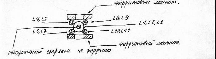
fig.1
The controller like in original progect(fig.2) ,coils L1 , L2 , L3
wound by wire 0,55 mm. on the pasteboard of diam. 18 mm.
Into this coil I insert two ferrite rods diam. 10 mm.,
l = 200 mm. to adjust the transformer.
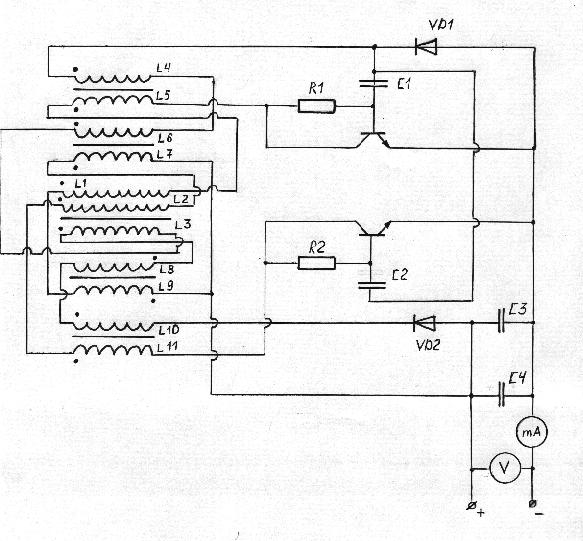
fig.2
The coils L4,L5 and L6,L7 ; L8 ,L9 and L10 , L11 wound on
ferrite rods with magnetic conductivity on Russian specification
standard M 400 HH diam. 10 mm. L = 200 mm. with two enameled
copper wires diam. 0,45 mm.The coils must be bifilar.( fig.3)
At the ends of the rods must be two ferrite magnets(I used
ferrite magnets from old loudspeakers)for adjusting the frequency
parametres of the transformer(see fig.3)
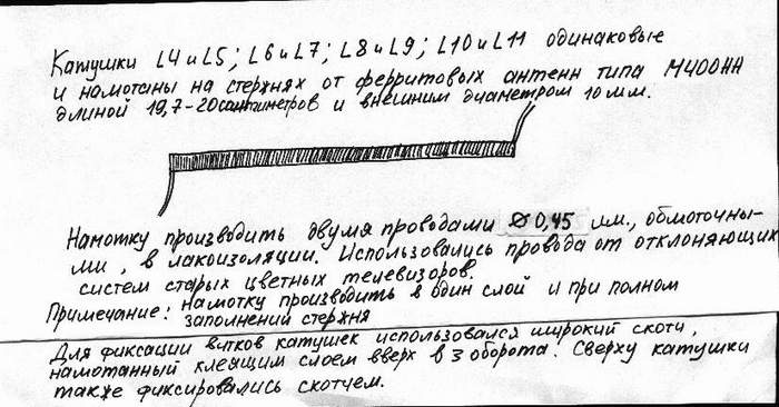
fig.3
At the ends of the rods must be two ferrite magnets(I used
ferrite magnets from old loudspeakers)for adjusting the frequency
parameters of the transformer(see fig.4)
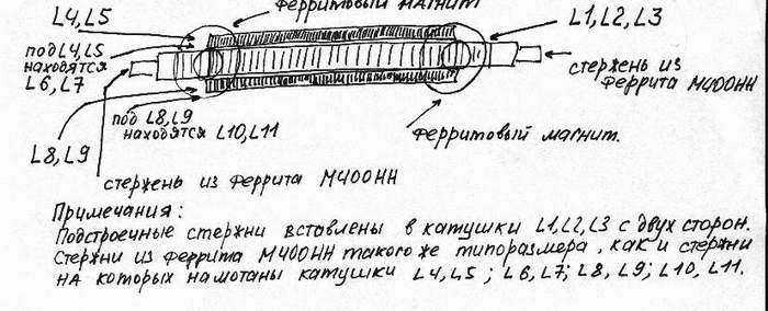
fig.4
The coil for the detector receiver is present in
fig.5
It wound on one of two magnets by enameled copper wire diam. 0,8 мм.
with 100 + 100 turns of bifilar winding.The connection coil
have 100 - 200 turns and at 30% from the ground have a tap to
trimmer capacitor 10 - 2000 pF.
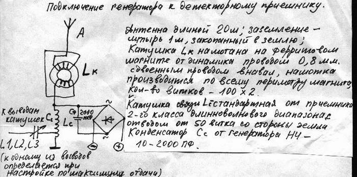
fig.5
At first I powered this circuit from laboratory
Volt.source 0,01 - 15V and max.current 1 A.I want to achieve better output from secondary ,but
KCE in all conditions ,with magnets or without, was 60 -80% .I deminish the voltage and see that
in small signal regime silicon transistors have better KCE.
Then I powered this device from the battery 1,5 V ,solar battery.
At the fird test I powered it from
detecor reciver with four stage multiplication of power on old germanium diodes.Later I make bridge rectifier on the same
diodes.I use antenna with length of 25 m.
If I adjust my receiver at the harmonic frequency of Shuman resonance
(in the range 75-500 kHz) or at one powerful LW station near Moscow,
I can obtain the output 2,3 V on electrolytic condenser 1000 mF with current 0,18 mA.With this small amount of power , I can hear the click
sounds
with interval of 2 - 15 Hz with maximum gain in 7,5 Hz at the ends
of adjusting rods in the central transformer coil.
I tuning that transformer to maximum output with two rods in central
coil and change the distance from magnets and the central part of the transformer.
If generation is no present - change the polarity of magnet.
Then I glue with epoxy adhesive two diffusors to the ends of ferrite rods,made from pasteboard.
The Tic-tak souns was very strong and I may hear them at next room.
This is useless designe,but this sounds make nervous tremor of my
cat and when I stay for long time near working device I want to sleep!
And this device may operate continually ,by years and years and only
static electricity from lightning may cause the damage for the semiconductors ...
![]()
![]()