![]()
The Doubled-triangle transformer.
In accordance with patent US4691746 "Flat windings ,
coil forms and
winding method" I want to make this doubled-triangle
(Jewish-star) transformer.
The direction of current flow (see the drawings of the patent)
make six vortexes , which make central vortex.
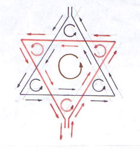
fig.1
I suggest to make transformation of that flat winding to 3D space,like in my drawing(fig.2)
The Doubled-triangle transformer schematicaly is shown in fig.2
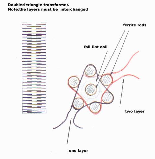
fig.2
In my opinion the central vortex have very low intercoupling with
six forming vortexes.So we can use energy of em-field from the coil,spaced in the central vortex.
I want to wound this transformer on ferrite rods . Changing the parameters of DC pulsing current we may turn central ferrite core to it's
main electrical (or both acoustical,depending of length of rod,and
electrical) resonances and with DMMT type or other special winding of coil we may extract energy from resonance stage of vortex!
DTT consists of primary winding and the secondary winding in form of flat spiral
(aluminium foil with polymer insulation) in one designe and the special coil in another.
In my intention I can use my controller to power this progect by DC pulses to obtain multiplied power from the coil spaced in the center of vortex.
Althow I can replace the coil of Ev.Gray tube by that transformer to achieve the best output from Ev.Gray system of energy conversion.
In fig.3 I show magnet transistor device using the doubled-triangle coil winding.
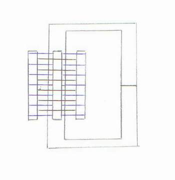
fig.3
The device may be with strong magnet like in MEG(fig.4)
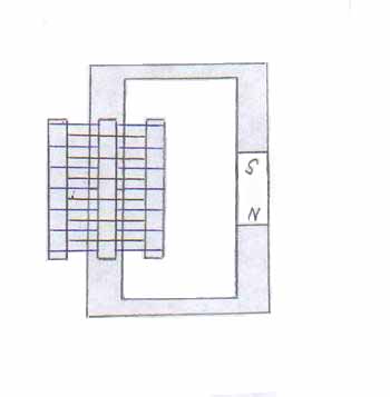
fig.4
![]()
![]()